- You'll need either an Arduino or an FTDI serial converter
- PuTTY can be used to monitor COM port serial messages
Alright. So you’ve purchased your ESP8266 thanks to the primer that I previously wrote, and you’re ready to start doing fun ‘Internet of Things’…things.
Before I go much further, I should let you know that I’m working with an ESP8266 ESP-12E. If you read the primer, you’re aware that there can be subtitle differences between the different ESP8266 variants, so keep this in mind as we move forward.

Powering the ESP8266
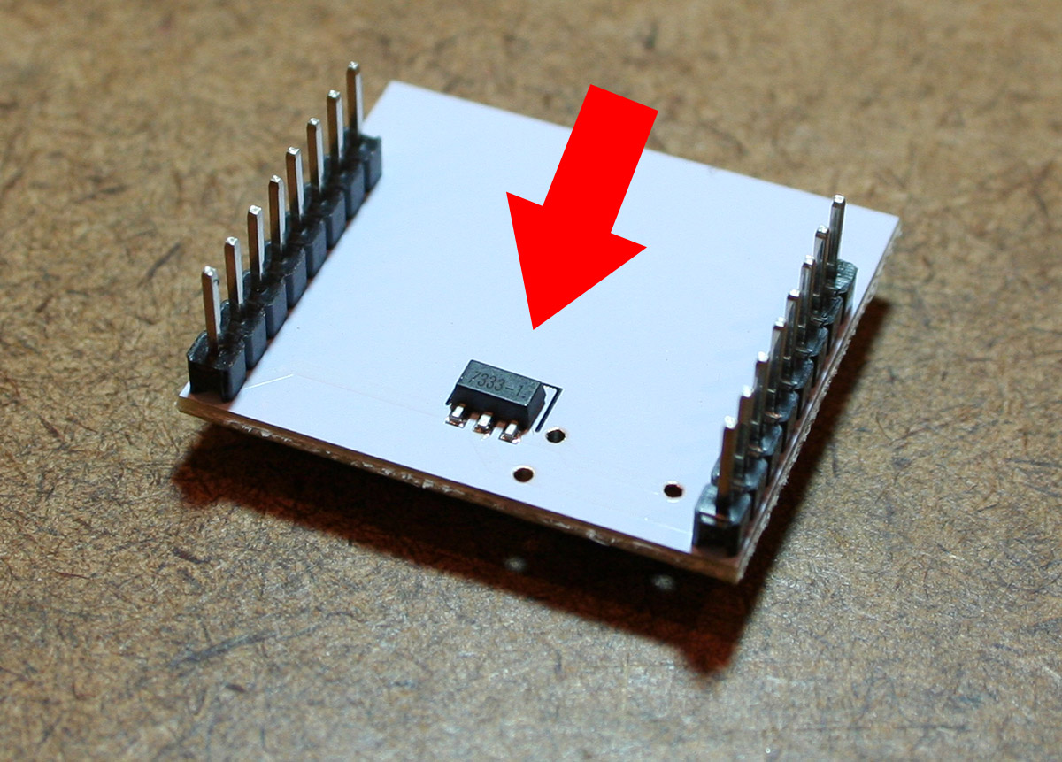
One thing that will not differ between the different variants is that they are all powered with 3.3 Volts. That being said, several of the chips that have been catered toward prototyping have additional hardware built in so that they’d be compatible with 5V power sources. For example, my ESP-12 adaptor board includes a 7333-1 voltage regulator, which, according to the datasheet, would accept up to 15V.
I personally have a bench power supply that I use to provide 3.3V to my ESP8266, but any source capable of delivering at least 250 mA at 3.3V should work just fine.
At this point, it makes sense to split up the rest of the post into two sections – for those of you that have an Arduino, and those of you that don’t.
Connecting to the ESP8266 with an Arduino
If you’re interfacing the ESP8266 with an Arduino, avoid powering the ESP8266 with the Arduino’s onboard 3.3V pin. Current ratings for the Aruindo’s 3.3V pin vary from model to model, but the popular Uno is only rated to supply 50mA through the 3.3V pin. I’ll get into this later, but the ESP8266 is capable of pulling more than 200 mA when it’s really working hard. Seriously, find an external power source.
Pin Connections
All we’re looking to do here is power on the ESP8266 and make sure it’s working properly. For that, we only need to connect a few pins. It’s counter-intuitive, but make sure that the TX pins are connected to each other, as are the RX pins. Also, be sure to tie the CH_PD pin to 3.3V. Before you connect the VCC and/or GND pins, we’ll first prepare the serial monitor so that we can see the ESP8266’s boot message.

Open a COM Terminal
There are a several ways to open up a terminal to monitor a COM port. If you’re using the Arduino IDE it’s as easy as going to Tools > Serial Monitor. The interface makes it pretty tough to open the wrong COM port, but you’ll want to make sure that you’re connecting to the correct one. In this case, my Arduino is connected to COM8.

Once the VCC and/or GND pins are connected, you’ll immediately see the ESP8266 dump a serial message to the monitor. If your baud rate isn’t set correctly, it will look like a bunch of gibberish. Most chips will default to 9600, but 115200 is popular as well. You’ll want to make sure ‘Both NL & CR’ is selected so that newline and carriage return characters are observed. In this case, the firmware that came included on my chip printed:
[code]Ai-Thinker Technology Co. Ltd.
ready[/code]
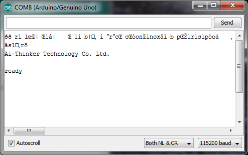
If you scroll all the way to the right and see a MEM CHECK FAIL!!! error, don’t worry too much about. It’s one of those undocumented quirks of the ESP8266 that no one’s exactly figured out yet.
Connecting to the ESP8266 without an Arduino
For those of you without an Arduino, you’ll need to have an FTDI USB-to-serial Converter, as described in the primer.
Pin Connections
Not all FTDI USB-to-serial converters are going to be the same, but for the OSEPP FTDI Breakout Board that I have, the pins connect as shown here.

Open a COM Terminal
Even if you don’t have an Arduino, you could still use the Arduino IDE, as described above, as a serial monitor. I wouldn’t really recommend that, though. You might as well use something like PuTTY. When you open PuTTY, you’ll need to set the radio button on the right to Serial mode. Once in serial mode, you’ll need to know the number of the COM port your FTDI converter is connected to. Additionally, the baud rate (Speed) needs to be set correctly. There’s no way of knowing exactly what the Speed should be set to without trial and error, but most firmware versions ship pre-set to either 9600 or 115200. You’ll know whether the speed is set correctly by whether or not you receive a bootup message after connecting the VCC and/or GND pins.


There you go! You’ve confirmed that your ESP8266 works! In the next section, we’ll take advantage of the chip’s wireless capabilities and connect to a local Wifi network.